Building (and Rebuilding) the QMX: Lessons from Three Attempts
The QMX from QRP Labs is a compact, multi-band QRP transceiver that delivers impressive performance in a very small package. It blends modern SDR concepts with the classic satisfaction of building your own radio — but it also demands patience, precision, and respect from the builder.
Today, I have two fully working QMX transceivers. Getting there, however, required three build attempts.
Attempt #1 — Total Failure (Magic Smoke Released)
My very first QMX build attempt was a complete catastrophe.
Somewhere along the way, a mistake slipped in, and during the initial power-up the board promptly released its magic smoke. At that point, the damage was beyond repair.
That board never made it on the air, but it delivered some unforgettable lessons:
- Rushing SMD builds is a bad idea
- Fatigue and poor lighting are serious risk factors
- Modern kits are unforgiving of small mistakes
QMX #1 (Working) — 60–15 m Version
My first working QMX is the 60–15 m version, purchased directly from QRP Labs.
While the build was largely successful, the radio exhibited a strange and persistent problem on receive: a constant audio tone at approximately 700 Hz, present even with no antenna connected and independent of band or RF gain settings.
This behavior strongly suggested a digital issue, rather than a problem in the RF path.
ADC Issues and the Constant ~700 Hz Tone
After systematic troubleshooting — including power checks, visual inspection, and configuration verification — the issue was traced to the ADC section.
A faulty or marginal ADC can introduce:
- Fixed-frequency tones
- Sampling artifacts
- Degraded or unstable RX behavior
In this case, the solution was to replace the ADC chip.
This delicate SMD rework was successfully completed with the help of Steffen, DO7FIR, to whom I owe a big thank you. After the replacement:
- The constant tone disappeared
- The RX noise floor returned to normal
- Overall audio quality improved noticeably
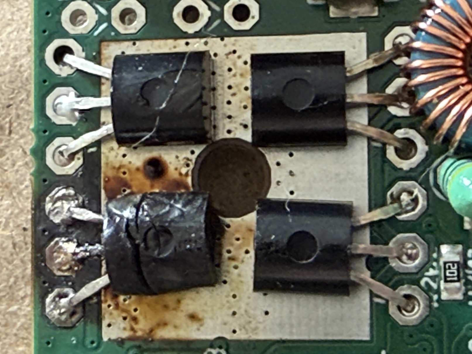
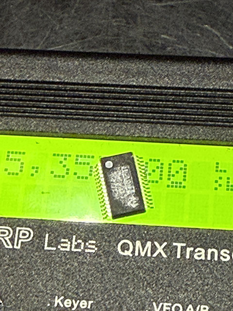 ADC chip replacement on the QMX 60–15 m board.
This fix resolved the constant audio tone issue and restored proper RX behavior.
Many thanks to Steffen, DO7FIR, for the help and steady hands.
ADC chip replacement on the QMX 60–15 m board.
This fix resolved the constant audio tone issue and restored proper RX behavior.
Many thanks to Steffen, DO7FIR, for the help and steady hands.
This QMX has since been operating reliably and has become a solid part of my QRP station.
QMX #2 (Working) — 80–20 m Version
The second working unit is the 80–20 m version, built as a deliberate second attempt after learning from previous failures.
This time, I approached the build very differently:
- I spread the work across multiple days
- I used good lighting and magnification at all times
- I followed the manual step by step, without shortcuts
The result was a perfect first power-up — no rework, no surprises. This radio worked exactly as expected from day one and confirmed that the QMX kit itself is excellent when built carefully.
QMX 2: On the bench
Recommendations for Future QMX Builders
If you’re planning to build a QMX (or any dense SMD kit), these recommendations are based on real-world experience:
🕒 Build Over Several Days
This is not a one-evening project. Stop when you feel tired — mistakes happen when focus drops.
📖 Read the Manual Carefully (More Than Once)
The QRP Labs documentation is excellent, but only if you actually follow it.
- Read each section before soldering
- Re-read it during the build
- Double-check component orientation and values
💡 Use Proper Lighting
Good lighting is not optional.
- Bright, even illumination
- Magnification if possible
- Your eyes — and your PCB — will thank you
🔍 Inspect Everything Before Power-Up
Before applying power:
- Inspect all solder joints
- Look for bridges and cold joints
- Perform all recommended measurements
Final Thoughts
The two QMX transceivers I have working today are the result of failure, repair, learning, and patience. The first board died dramatically, the second needed expert help, and the third rewarded a careful and methodical approach.
Would I build another QMX? Without hesitation.
If you’re considering one: slow down, respect the kit, and enjoy the process.
73